|
(Tag: visualeditor-switched) |
| Line 181: |
Line 181: |
| | | | |
| | === Mathias Research Ranch Installation in Alberta, Canada === | | === Mathias Research Ranch Installation in Alberta, Canada === |
| − | <gallery mode="packed" heights="400"> | + | <gallery mode="packed" heights="300"> |
| | File:20190918_123513.jpg| | | File:20190918_123513.jpg| |
| | File:20190918_123550.jpg| | | File:20190918_123550.jpg| |
| | File:20190918_123612.jpg| | | File:20190918_123612.jpg| |
| | </gallery> | | </gallery> |
Revision as of 15:06, 24 October 2019
The power supply recommended for AC powered installations where the observatory is located close to the AC power supply is the Meanwell GST120A12.
For observatories with heaters and long DC power cable runs the Meanwell HRP-300-12 is recommended as it's remote sense functionality allows it to compensate for any voltage drop in the long cable runs. (If no heaters are present, the Meanwell HRP-150-12 is the preferred option.)
Direct links to order Meanwell HRP-300-12 from USA:
HRP-300-12, Mouser Electronics
HRP-300-12, TRC Electronics
Accessories for Meanwell HRP-300-12:
TRC-E-HRP300450600 enclosure for HRP-300-12
US/Canada power cord for HRP-300-12
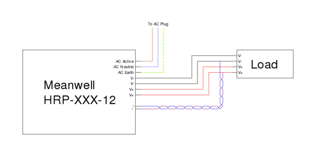
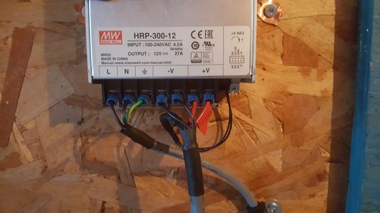
Power supply wiring with remote sense for long cable runs.
Outdoor Cable
The recommended off the shelf for use on roofs or outdoor structures is the sunlight and abrasion resistant AlphaWire EcoFlex PUR 80045 SL005 (unshielded) or 80145 SL005 (braid shield). Digi-Key usually has one or the other in stock: 80045 SL005, 80145 SL005.
That cabling doesn't have a twisted pair, so we recommend wiring up the conductors to the green numbering in the two images below.
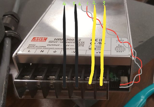
Recommended wiring on the power supply side for a 6 or 7 conductor cable (twisted pair will most likely not be present in off-the-shelf cables) You should use
Blue 3mm Fork Crimps to terminate the conductors for L,N,E,-V and +V. This power supply should be installed in a metal enclosure which should be connected via grounding studs to the Earth terminal. The enclosure's door or access panel also needs to be connected. See the Meanwell HRP datasheet for sense connector details.
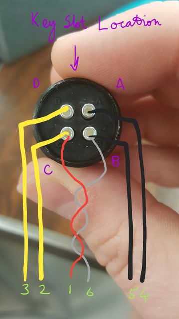
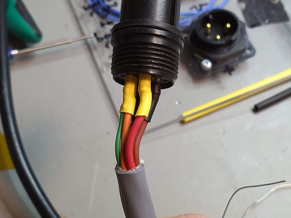
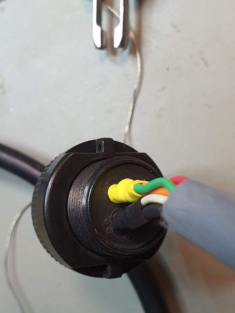
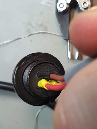
Recommended wiring on the observatory power plug side for a 6 or 7 conductor cable (twisted pair will most likely not be present in off-the-shelf cables) Conductors 1 and 6 will need to be soldered to the side of C and B if thick conductors are used. The transition from insulated wire to contact needs to be covered by heat shrink to prevent short circuits if the cable subject to twisting torques.
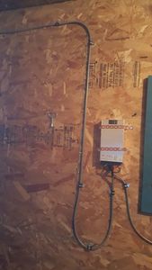
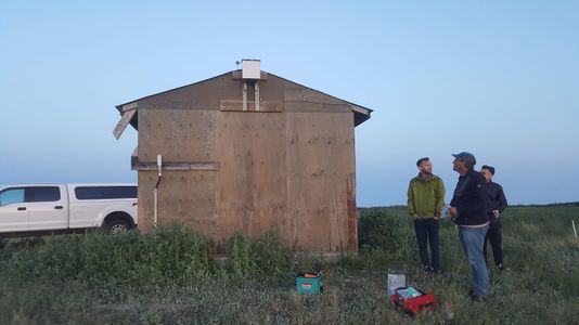
Mathias Research Ranch Installation in Alberta, Canada
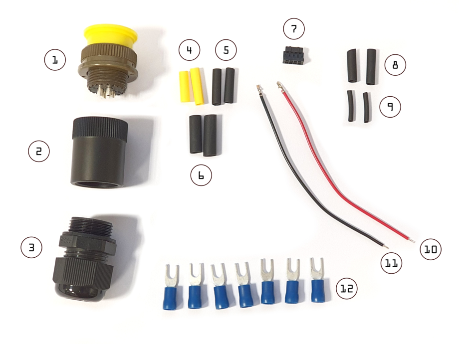
Long DC Cable Run Connector Care Package
If you need to build your own long cable with (using the cable listed above) you can request a Long DC Cable Run Connector Care Package from us. It should contain:
Long DC Cable Assembly
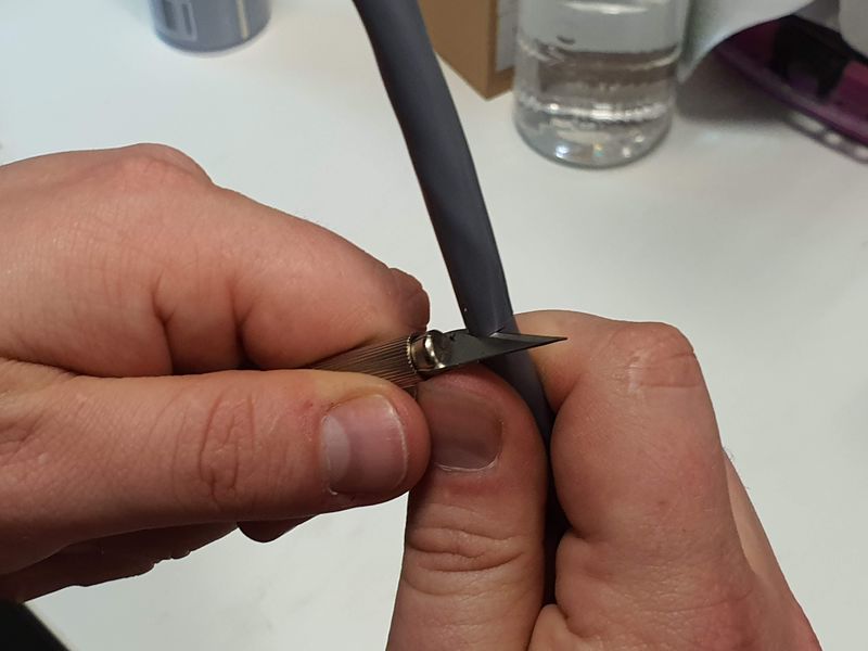
Cut around cable jacket about 50 mm back from cable end, careful only to cut jacket and do not nick wire insulation. If you do nick wire insulation, cut off section and start again.
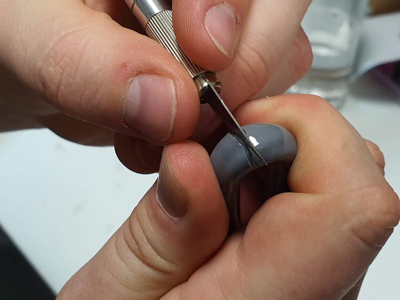
Bend cable and carefully slice away jacket without nicking wire insulation. If you do nick wire insulation, cut off section and start again.
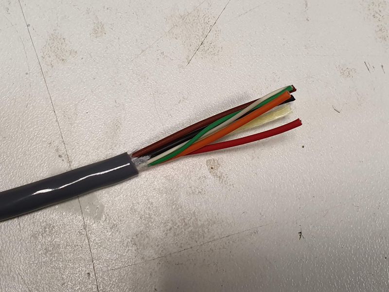
Pull off jacket to reveal wires.
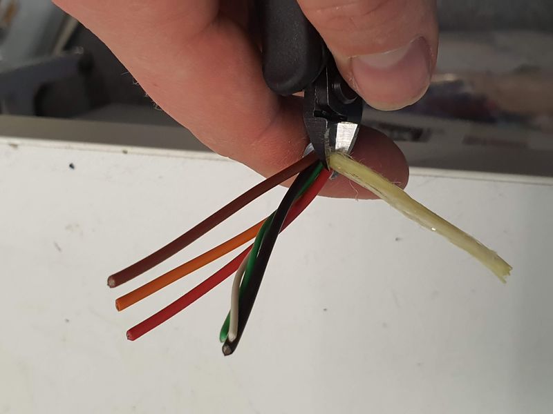
Cut fibrous centre reinforcement.
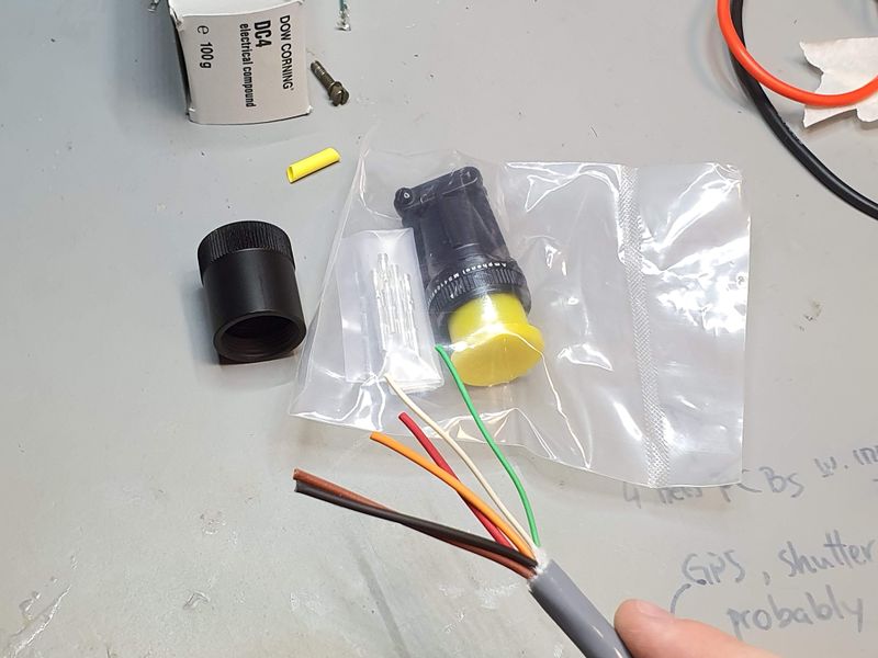
End should now look like this.
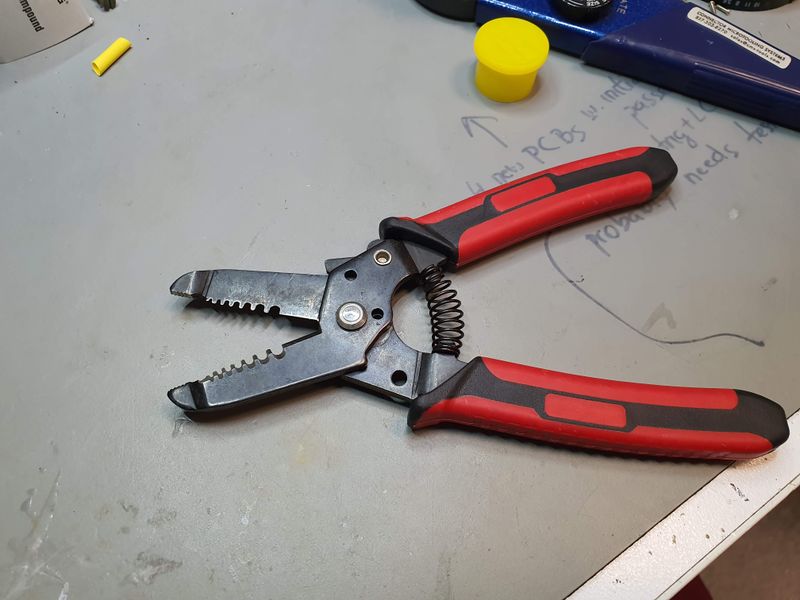
This sort of wire stripper and cutter is recommended. Ensure it is sharp otherwise you'll have a hard time inserting the mangled conductor into the crimp contacts.
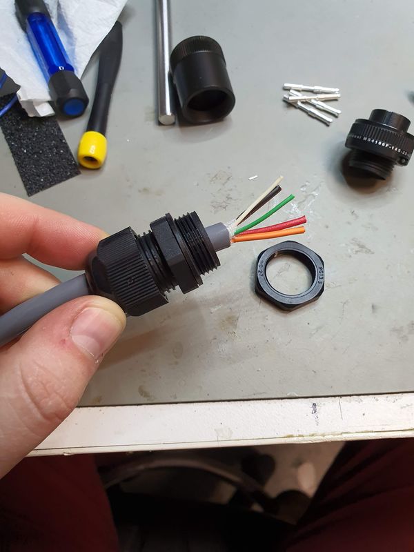
Trim wires back using wire cutters and place cable gland (without nut) onto cable.
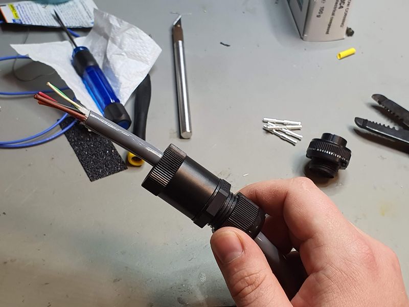
Place cable gland adaptor on cable and screw together with cable gland.
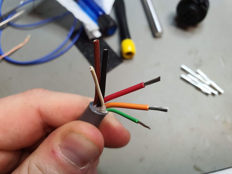
Strip ends for crimp contacts.
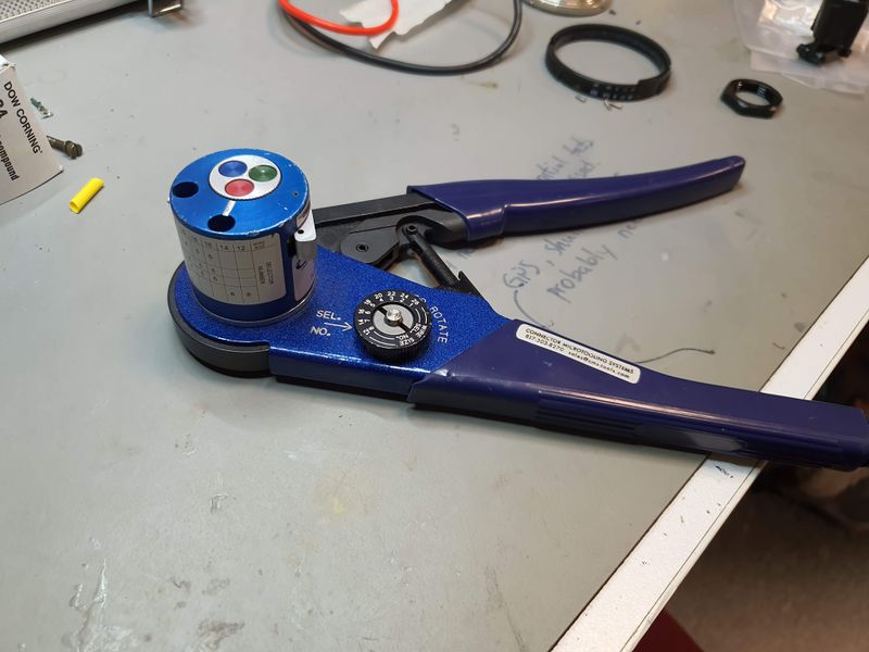
Use the correct crimp tool for the contacts, or solder the connections. Pliers won't work.
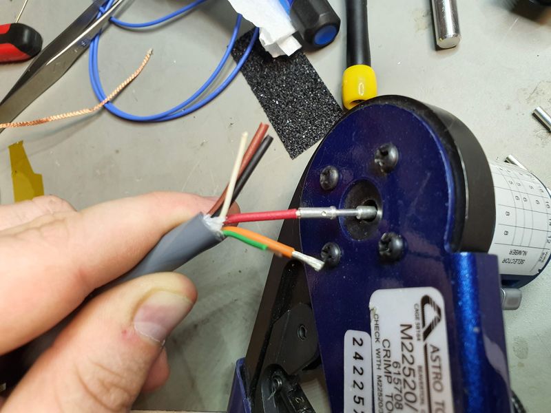
Set your crimp tool to the correct setting on the coloured wheel on the back (red on ours). Insert your crimp contacts into the tool.
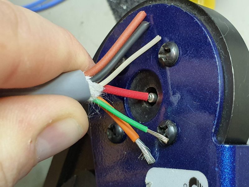
Ensure the contact is fully inserted and crimp fully without stopping.
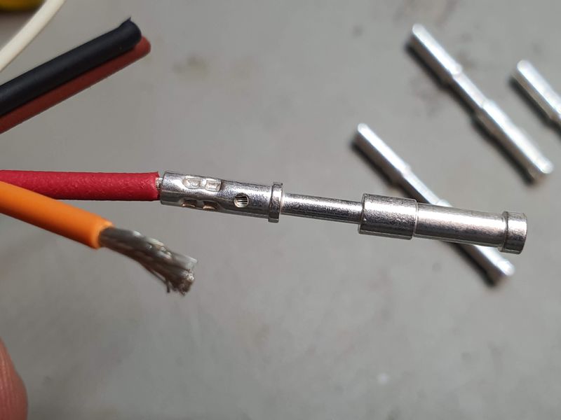
This is what a good crimp looks like. Ensure the wire is visible in the hole. If not, then you didn't strip enough insulation of or insert the wire deep enough.
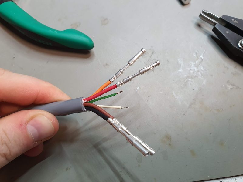
Crimp the other power contacts.
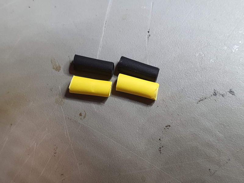
Cut ≈10 mm lengths of 3 or 5 mm heatshrink tubing, yellow for +12V and black for GND.
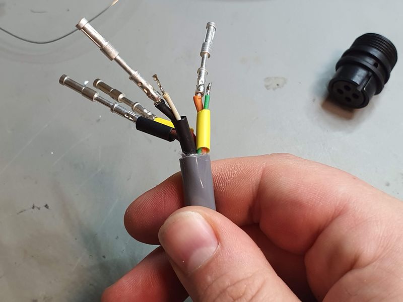
Place the heatshink over the wires, taking care to use the correct colours (yellow for +12V and black for GND) and to bundle the voltage sense wires inside the heatshrink with their corresponding power contacts (which they will be soldered to later).
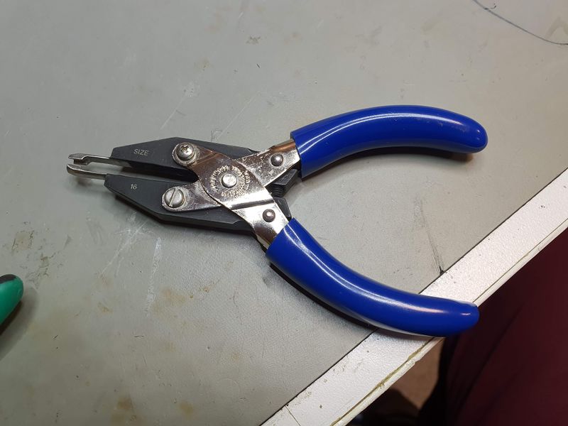
Use the contact insertion tool to push the contacts into the plug.
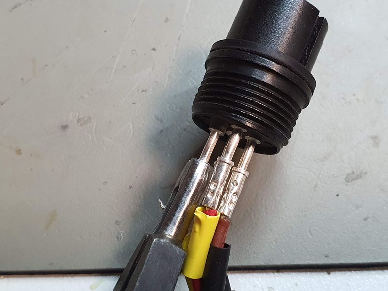
Insert the contacts, grip around the skinny part initially before moving back to the crimp part to avoid bending the contacts. If you do bend the contacts, cut the wires and start again. Do not straighten bent contacts.
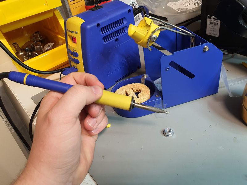
We will now use our soldering station to solder the voltage sense wires to the power contacts.
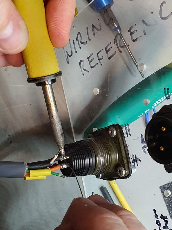
Place a blob of solder on the side of the crimp part of the two power contacts where the voltage sense wires will be attached.
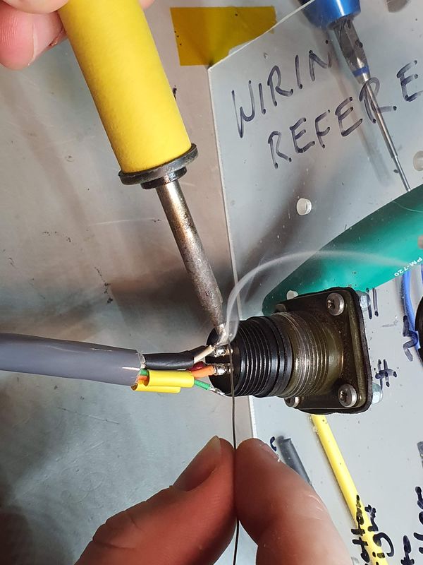
Tin the voltage sense wires.
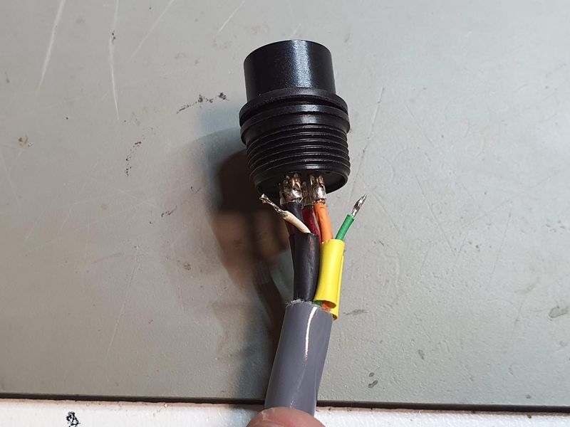
Your connector should now look like this.
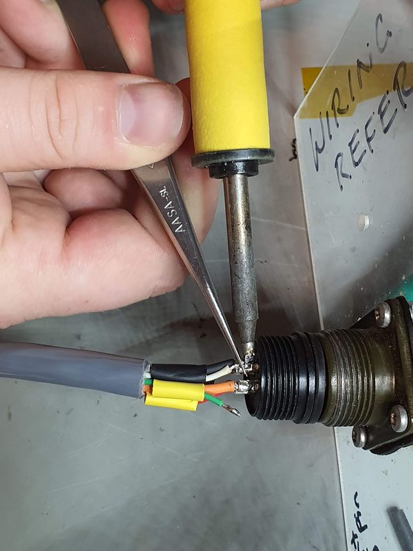
Press the wire to the contact with tweezers and reflow the solder to make the connection.
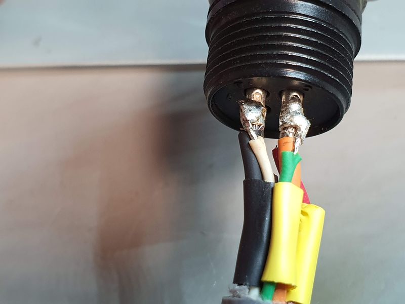
Your connector should now look like this. The solder joints should look smoother and shinier than this though.
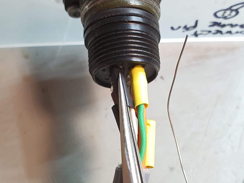
Push the heatshrink tubing up to cover the contacts.
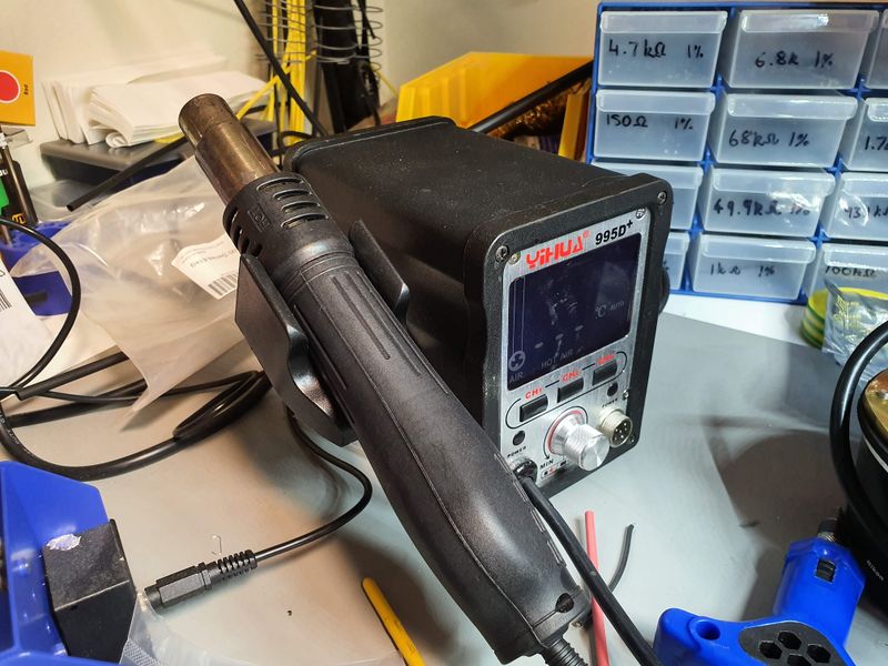
We will now use a hot air station to shrink the heatshink tubing. You can use a hot air gun or a lighter instead.
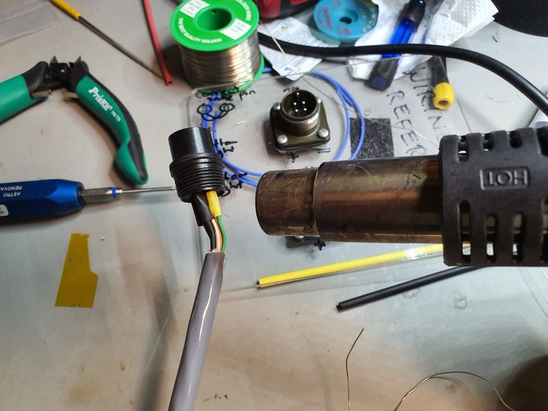
Shrink the tubing with hot air. Take care not to melt the insulation.
Your connector should now look like this:
Mathias Research Ranch Installation in Alberta, Canada


